2080 BhadraChapter 1: Introduction1.2 Power Potential in Nepal and World, Gross, technical and economic potentials
Briefly discuss the institutional set up in hydroelectricity development in Nepal with flow chart. [4]
TU IOE · CE 704
Briefly discuss the institutional set up in hydroelectricity development in Nepal with flow chart. [4]
How do you estimate the gross and net hydropower potential between two sections of the river? [4]
Outline the challenges for hydropower development in Nepal. Discuss hydropotential in Nepal. [2+2]
Answer the following: (i) What are the top three hydropower producing countries in the world till 2020? (ii) What are the three existing largest power plants in Nepal (with capacity)? (iii) What are the first three hydropower plants (capacity and year) from the history of Nepal? [4]
Discuss about the advantages and disadvantages of hydropower projects comparing to other sources of energies. [6]
Discuss the advantages and disadvantages of hydropower over other sources of energy. [3+3]
Briefly discuss the historical development of Hydropower in Nepal. [3]
What are the opportunities and challenges for Hydropower development in Nepal? Write your comments on the Hydropower Development Policy-2001 of Nepal. [4+2]
Explain briefly the procedure for obtaining Licenses for Hydropower development of 5 MW RoR hydropower project as per the provision of hydropower development policy 2001. [4]
Discuss about the objectives and strategies of the hydropower development policy 2001. [3+1]
Discuss the objectives of the Hydropower Development Policy 2001? List out the major provisions in hydropower development sector. [3+3]
What are the objectives of the Hydropower Development Policy, 2058? List out various hydropower development institutions in Nepal. [4+2]
Describe briefly the provision for licencing of Hydropower according to Hydropower Development Policy Nepal, 2058. [6]
Discuss the Hydropower Development Policy 2058 of Nepal. [6]
What are the objectives of Hydropower Development Policy 2001? Explain five main features provisioned in Hydropower Development Policy 2001 for the development of hydropower in Nepal. [3+3]
List out the major features of Hydropower Development policy 2001. Is the policy able to attract private sector? Write your comments. [6]
"Most of the political parties of Nepal are determined to avoid Load Shedding during 5 years in their menufesto." Do you agree with their commitment during this period? What approach need to be taken for hydropower development in Nepal to meet the demand rate up to 2020? [2+3]
Name the major institutions involved in hydropower development sector in Nepal. Briefly outline the hydropower development policy of Nepal. [4]
Discuss the key features of Nepal's Hydropower Development Policy of 2058 BS. [4]
Briefly describe the importance of hydropower development in Nepal. [4]
List the various government organizations involved in the development of the hydroelectric power sector in Nepal and describe their responsibilities. [1+3]
Explain the working principle of RoR, PRoR and ST plants with the help of figures. Also comment on the suitability of those plants in the context of Nepal. [6]
Sketch and explain layouts of the run of river plant. Also explain the importance of storage hydropower plants over run of river plant. [3+3]
Describe various types of hydroelectric scheme based on hydraulic characteristics. [4]
Explain the different types of hydropower plant based on head, turbine characteristics, and load characteristics. [2+2+2]
Describe the importance of storage hydropower projects in Nepal. Sketch the general layout of pump storage plant. [3+2]
Mention different phases of hydropower development cycle. What factors do you consider in pre-feasibility and feasibility study of hydropower projects? [2+2+2]
Explain different phases of hydropower development cycle. Draw the layout plan and section of RoR type hydropower project with headrace canal. [4+4]
Discuss hydropower development cycle with flow chart. Explain the type of studies done in detailed engineering design stage of hydropower project. [2+4]
Discuss hydropower development cycle with flow chart. Draw the layout plan and section of a storage hydel plant with power house. [4+4]
What are the various stages of hydropower planning? If you have been appointed as a water resources engineer in Water Resources Ministry and you are assigned to undertake various investigations related to water resources field. Discuss field investigations you carry out at various stages of the hydropower project. [2+6]
Discuss about the objectives and strategies of the Hydropower Development Policy-2001 (2058 BS) of Nepal. [6]
Highlight the major studies and investigations carried out during reconnaissance, prefeasibility and feasibility studies. [8]
Differentiate between pre-feasibility and feasibility studies of a hydropower project with explaining the site specific hydrological and topographical investigations. [8]
If you are developing 10 MW RoR hydropower project in Nepal, write different studies carried out during the feasibility level study. [5]
What are the stages of hydropower development cycle? [2]
Explain site specific hydrological, geological and topographical investigations to be carried out at the pre feasibility study level of a hydropower project. [5]
What are the different stages of hydropower development? Explain the working principle of peaking run off river plant and show general arrangements of components with neat sketches. [2+3+3]
Discuss briefly the hydropower development cycle. [2]
Prepare a three alternative layouts plan and sectional drawings of the ROR Hydropower plants. What are the stages of hydropower development cycle? [6+2]
Suppose you are a senior consultant engineer with the responsibility of being the team leader for a small hydropower project. Describe the steps and activities that your team must carry out to conduct a feasibility study for this hydropower project. [8]
You are developing 300 MW reservoir type project in a river basin of Nepal. Briefly mention what steps you would follow from planning to commissioning of the project. [5]
Discuss hydropower development cycle with flow chart. [2]
How do you optimize the plant capacity of a RoR Project? Discuss. [4]
Draw a neat sketch showing the typical arrangement of components of a headworks of a RoR hydropower project. Write down the importance of its intake. How do you decide the location of an intake in a river? [2+2+2]
Draw a general layout of the powerhouse using a vertical axis Francis turbine. [4]
Draw a layout (plan and section) of ROR hydro project for following cases: (i) Alignment with pressure tunnel (ii) with free surface flow. Name salient features also (draw with representative contours). [6]
Draw a general layout (plan and section) of the diversion type hydropower project. Comment on the suitability of the Run of River (RoR), Peaking Run off River (PRoR) and Storage projects in Nepal. [3+3]
A RoR plant has a minimum flow of 30 m³/s and net head of 70 m. The overall efficiency of plant is 85%. Calculate the installed capacity of the plant (i) Without pondage (designed for pure RoR plant) and (ii) If the plant is designed for a peaking plant with 6 hours peaking. The plant has two sets of units such that one unit full capacity if operating during off peak hour. Total evaporation and other losses is 5% of the stored water. [6]
Drawing neat sketch (plan and section with all components), discuss the principal characteristics of diversion type storage hydropower plant. [4]
A hydropower plant is planned to be designed in Nepalese river, where mean monthly flows for a typical year are as follows [table with monthly flow, design discharge, full supply level, turbine centerline, tunnel & penstock diameters, efficiencies]. Considering only frictional loss, compute installed capacity, primary and secondary energy to be produced from the power plant assuming that 10% minimum monthly flow to be released downstream. What is the plant factor? The developer is interested to develop a daily peaking reservoir for 4 hours. What will be the capacity of the reservoir to satisfy daily peaking requirement? [2+2+2+2, 4]
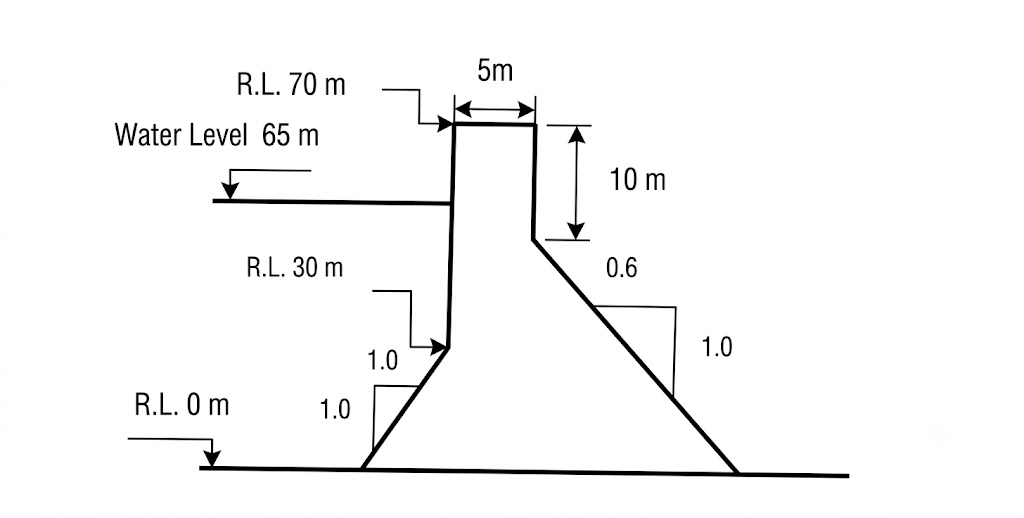
A concrete gravity dam has a specific gravity of 2.4 has the dimensions as shown in the figure below. Neglect all other forces except self-weight, hydrostatic force, and uplift pressure. The friction coefficient between the base and foundation of dam is 0.70, the coefficient of uplift pressure is 0.5, and the allowable crushing strength and tensile strength of dam materials are 30 kgf/cm² and 5 kgf/cm², respectively. Check the stability of dam. [12]
The stream flow record for a hydropower development site is given below. Draw a flow duration curve and determine firm and secondary energy if the available head is 60 m. design discharge capacity is 45 m³/s and overall efficiency is 82%. [8]
In a Nepali river the mean monthly flow in a year 2021 is given below. a) Draw the flow duration curve. b) The power available at mean flow of water if available head is 100 m at the site and overall efficiency of the plant is 85%. [4+4]
Table below shows the inflow for one reservoir. i) By assuming the mean inflow as the draft, develop mass-curve of the reservoir. ii) Determine storage capacity and length of critical period. iii) Determine storage capacity if the draft is only 80% of the mean inflow and compare with storage capacity of (ii). [12]
What do you mean by mass curve? Write step wise procedure of calculation of reservoir capacity using the mass curve. [1+3]
During a low water week a river has an average daily flow of 40 m³/s with a fluctuation during the day required a pondage capacity of approximately 30% of the daily discharge. A hydroelectric plant is to be located on the river which will operate 6 days a week, 24 hours a day, but will supply power at a varying rate such that the daily load factor is 50%, corresponding to which the pondage required is equal to 0.2 times the mean flow to the turbine. On Saturday all the flow is ponded for use on the rest of the days. If the effective head on the turbines when the pond is full to 25 m and the maximum allowable fluctuation in pond level is 1m, find (i) the surface area of the pond to satisfy all the operating conditions (ii) the weekly output at the switch board in kwh. Assume turbine efficiency 80% and generator efficiency 90%. [5+5]
The monthly flows of a stream over the period of the driest year on record are shown below [table]. (i) Estimate the maximum possible uniform draw-off from this stream and determine the reservoir capacity to achieve the uniform draw-off and the minimum initial storage to maintain the demand. (ii) If the reservoir has only a total capacity of 8×10⁶ m³ with an initial storage of 4×10⁶ m³, determine (a) the maximum possible uniform draw-off and (b) the spillage. [7+3+2]
What do you mean by sediment yield and life of a reservoir? Explain various remedial measures that help to reduce the reservoir sedimentation. [1+3]
A hydropower plant is to be planned in a Nepalese river, where the mean monthly flows for a typical year are as follows:
| Month | Jan | Feb | Mar | Apr | May | Jun | Jul | Aug | Sep | Oct | Nov | Dec |
|---|---|---|---|---|---|---|---|---|---|---|---|---|
| Q(m³/s) | 4.4 | 3.9 | 3.4 | 4.2 | 5.6 | 16.5 | 78.1 | 108.9 | 52.8 | 22.0 | 9.9 | 6.4 |
Other data pertaining to the plant are as follows: Design Discharge = 18 m³/s; Full Supply Level = 2250 masl; Turbine Center line = 1650 masl; Dia of 4.0 km long tunnel = 3.0 m, f=0.014; Dia of 1.0 km long penstock = 2.2 m, f=0.012; Hydraulic Efficiency = 95%; turbine efficiency = 93%; Generator Efficiency; Transformer efficiency = 99%. Considering only Frictional loss, a) Compute installed capacity, primary and secondary energy to be produced from the power plant assuming that 10% minimum flow to be released downstream. What is plant factor? [5+2] b) The developer is interested to develop a daily peaking reservoir for 4 hours. What will be the capacity of the reservoir to satisfy daily peaking requirement? [3]
A RoR hydropower plant is proposed in a river. Using marginal cost and benefit method optimize the installed capacity with following data: Interest rate = 12%; Energy price = $0.08/Kwh; Fixed cost = $60×10⁶; Variable cost (Electro-mechanical) = $650/KW; Annual O/M = 3% of variable cost; Project life = 35 years [table with %Time vs Power(KW)]. [8]
A hydropower plant is planned to be designed in Nepalese river, where mean monthly flows for a typical year are as follows:
| Months | Jan | Feb | Mar | Apr | May | Jun | Jul | Aug | Sep | Oct | Nov | Dec |
|---|---|---|---|---|---|---|---|---|---|---|---|---|
| m³/s | 4.4 | 3.9 | 3.4 | 4.2 | 4.2 | 16.5 | 78.1 | 108.9 | 52.8 | 22.0 | 9.9 | 6.4 |
Other data pertaining to the plant are as follows: Design discharge = 18 m³/s; Full supply level = 2250 masl; Turbine centerline = 1650 masl; Dia of 4 km long tunnel = 3 m, f=0.014; Dia of 1 km long penstock = 2.2 m, f=0.012; Hydraulic efficiency = 95%, Turbine efficiency = 93%, Generator efficiency = 99%, Transformer efficiency = 99%. Considering only the frictional loss, (i) Compute installed capacity, primary and secondary energy to be produced from the power plant assuming that 10% of minimum monthly flow to be released downstream. What is the plant factor? [2+2+2+2] (ii) The developer is interested to develop a daily peaking reservoir for 4 hours. What will be the capacity of the reservoir to satisfy daily peaking requirement? [4]
The mean monthly flows of a river in a typical dry year are as follows [table]. Other data: prevailing interest rate=12%, Energy selling price=Rs 5000/Mwh and 3000/Mwh for primary and secondary energy, installation (Electro-mech) cost = Rs 80000/kW, project life time = 40 yrs, overall efficiency of the plant = 87%, Effective head = 100m, O&M cost = 2% of electro mechanical cost, fixed cost = Rs 30×10⁹. a) Determine the installed capacity of such plant. b) Calculate the firm power of the plant, considering 95% probability of exceedance of flow. c) If the deficit in the firm power in the power system is 200 MW what is the storage capacity of reservoir to satisfy the demand. [5+2+2]
Hydropower project is planned to develop in a river having net head of 100 m and overall efficiency of 85% with the monthly hydrograph as shown below:
| Month | Jan | Feb | Mar | Apr | May | Jun | Jul | Aug | Sep | Oct | Nov | Dec |
|---|---|---|---|---|---|---|---|---|---|---|---|---|
| Discharge | 100 | 120 | 140 | 300 | 320 | 1800 | 2000 | 2500 | 2100 | 900 | 500 | 300 |
i) Calculate installed capacity, annual spill energy and firm energy if RoR project is designed based on the 40% probability of exceedance flow. ii) If the storage project is developed with full regulation of annual hydrograph (design discharge is equal to average monthly flow), Calculate the storage requirements. iii) Calculate the installed capacity and annual energy generation from the storage project as mentioned in above case. [2+2+2+2]
The mean monthly flow of a river in a typical year are as follows [table]. The effective head of the ROR plant is 48 m and can be assumed constant. Other data: Fixed cost: USD 2795×10⁶; Variable cost: US$ 645/kW; Annual O&M cost: 2.5% of variable cost; Energy price: US$ 38/Mwh for primary and secondary energy; Interest rate: 11%; Economic life of the project: 45 years; Overall efficiency: 89%. Determine the best installed capacity, firm energy, secondary energy, total energy, and plant factor. [9]
The mean monthly flows of a river in a typical year are as follows [table]. The gross available head is 229 m, and the average head loss in transition is 12m. The efficiencies of the turbines, gearboxes and generators are 94%, 92% and 99% respectively. 10 m³/s of water must be left in the river for downstream users. Other data: Fixed cost: US$1200×10⁶; Variable cost (present worth value): US$500/kW; Energy price: US$48/Mwh for primary and secondary energy; Interest rate: 12%; Economic life of the project: 50 years. Determine the best installed capacity, firm energy, secondary energy, total energy and plant factor of a run-of-river plant. [10]
A hydropower project is planned to develop in a Nepalese River having net head of 150 m, turbine efficiency of 90% and generator efficiency of 95% with the monthly hydrograph as shown below:
| Months | Oct | Nov | Dec | Jan | Feb | Mar | Apr | May | Jun | Jul | Aug | Sep |
|---|---|---|---|---|---|---|---|---|---|---|---|---|
| Q (m³/sec) | 100 | 80 | 60 | 50 | 40 | 30 | 40 | 50 | 70 | 110 | 150 | 120 |
As an environmental flow, a minimum flow of 10% of each month is mandatory. If the storage project is designed with full regulation of annual hydrograph, find out: the capacity of the reservoir; installed capacity of the power plant, and annual energy generation. [3+2+3]
A hydropower plant receives design discharge of 25 m³/s from 150 m height. The annual output of the plant is 220 GWh. If the peak load demand is 30 MW, determine (i) annual load factor (ii) Capacity factor and (iii) Utilization factor. Assume overall efficiency of the plant equals to 85% and neglect head loss in the penstock. [2+2+2]
A peaking ROR project in western Nepal with net head of 250m has following river flow data:
| Month | Jan | Feb | Mar | Apr | May | Jun | Jul | Aug | Sep | Oct | Nov | Dec |
|---|---|---|---|---|---|---|---|---|---|---|---|---|
| River flow (m³/s) | 100 | 80 | 80 | 105 | 200 | 500 | 1100 | 1200 | 800 | 350 | 200 | 120 |
The storage capacity available for this project is 1100 million m³. This storage capacity is utilized for dry months (Nov-May) during which the plant is used as peak load plant 4 hours a day. Considering design flow as Q25, calculate maximum power generation (in MW) and ratio of wet season energy to dry season energy. [12]
A hydropower electrical project has a concrete lined tunnel of 5.0 m diameter operating under a gross head of 200 m. Discharge through tunnel is 28 cumec and having surge tank of 300 m² at the end of tunnel. Head loss due to friction under a steady state condition is 2.5% of gross head. Assume friction factor of tunnel to be 0.015. Find Total length of tunnel; Maximum upsurge and downsurge in the tank; Calculate factor of safety of surge tank. [6]
The power supplied by the state electricity authority throughout the year by steam power plant are as shown in table below [Month, Power Supplied(MW)]. But the current demand forced them to have loadshedding. To minimize the loadshedding by providing at least power equivalent to Magh month throughout the year, Authority has decided to import power from neighbouring country for only 3 months i.e. Falgun, Chaitra and Baisakh as 50 MW, 55 MW and 100 MW respectively. a) Despite importing power, authority felt that they can not provide uniform power of Magh throughout. So they decide to have a diesel plant for deficit. Estimate the minimum capacity of diesel plant. (Use load duration curve for analysis) b) If instead of above system (Steam plant + import + diesel plant), Authority has planned to provide power in near future by constructing ROR hydropower plant by its own to substitute the current model. Derive the Flow duration curve for such new hydro project to supply the power demand given in table. Assume power demand is constant in future. [5+5]
In a minigrid the average load variation is recorded as [table: Time, Load(KW)]. Power is supplied by the plant capacity of 950 KW Micro-hydro. Find out load factor, plant capacity factor and utilization factor. [3]
What are the factors to be considered in the dam site evaluation? Describe the different failure modes of a gravity dam. [4+4]
Discuss the selection criteria of different types of dam in hydropower projects. What type of dam do you select in different foundation condition? [3+2]
Explain causes of failure of earthen dam. What criteria do you adopt for safe design of earthen dam? [2+4]
Define elementary profile of a gravity dam. How do you proportionate the dimensions of an elementary profile if the reservoir is full? [1+5]
Determine the basewidth of a 20m high trapezoidal concrete dam having a vertical upstream face and top width of 5m. Design water depth is 18m. There is no tail water. Ignore earthquake, silt and ice loads. Take e=B/6, σconcrete=30MPa, σfoundation=80MPa, τs=6MPa. Specific weights of water and concrete are 10kN/m³ and 24kN/m³ respectively. Assume suitable data, if necessary. [6]
Calculate the forces and the principle stress and the shear stress at the toe and heel of the gravity dam section shown below. Check the dam against sliding, crushing, overturning and tension. Do not consider the forces other than self-weight, hydrostatic pressure and uplift pressure. Assume allowable compressive stress for the material of the foundation is 50 kg/cm², allowable crushing stress for the material of the dam body is 10.5 kg/cm², friction coefficient is 0.70 and uplift coefficient is 0.45. [12]
A concrete gravity dam has the following data: Maximum water level = 550.00; Bed level = 470.00; RL Top of Dam = 554.00; The d/s slope of 0.67:1 and starts at RL of 545.00; US face is vertical; Centre line of drainage gallery – 8.0 m from the u/s face; Consider only weight, water pressure and uplift. Calculate the maximum vertical stresses at the toe and heel of the dam. Also calculate factor of safety against sliding and over turning. Assuming 100% uplift pressure at heel, 50% at drainage gallery and zero at the toe. Take μ=0.75. [10]
Section of the gravity dam is shown below. i) Calculate maximum vertical stresses at the heel and toe of the dam. ii) The major principle stress at the toe of the dam. iii) Calculate factor of safety against overturning and sliding. Take γc=24 kN/m³ and σa=2500 kN/m². [10]
Discuss about the "Middle third rule" in the design of concrete gravity dam? Describe with necessary derivation. [6]
Show that the resultant force in a concrete gravity dam should pass within the middle third of the base width in order to avoid tension in the heel. [6]
A concrete gravity dam of given profile is purposed by a designer for implementation. The unit shear resistance and angle of resistance is 500 KN/m² and 35° respectively. γcon=24 KN/m³, check the stability of dam against flotation, overturning and sliding. [8]
Check the stability of the overflow section of the gravity dam shown in figure. Assume the weight of concrete, gates, piers and weight of water over crest, Wtotal=3.0×10⁴kN. Moment of weight of concrete, gates, piers and water above crest etc. about toe Mtoe=10⁶ kN-m. Neglect all forces other than weight, uplift pressure and water pressure. Also check for tension. Take μ=0.75 and q=1400 kN/m². [10]
A concrete gravity dam (trapezoidal in section) has height 20 m, top width 1.2 m and bottom width 10 m is proposed to block the water of height 18 m. The u/s face of the dam is vertical and the d/s face has slope 1:2 (H:V). Considering the forces: self weight, hydrostatic force and uplift pressure, check the stability of the dam. (Assume unit weight of concrete=24 KN/m³, permissible shear stress of joint as 1400 KN/m², coefficient of friction as 0.75, and uplift factor k as 0.8). Neglect the tail water effect to the dam. [8]
A concrete gravity dam on the rocky foundation is acted by the upstream horizontal hydrostatic force of 4.50 million KN and by the downstream the same of 0.50 million KN. Determine the volume of concrete works (γcon=24 KN/m³), neglecting bond stress and up lift force and taking a factor of safety on the horizontal thrust of 2.5 and a friction coefficient between the concrete and rock of 0.65. [8]
Determine the principal stresses at the toe and heel of the dam shown in figure for the reservoir full conditions. Consider the following forces: (i) Self weight (wc=25kN/m³) (ii) Water pressure (w=10kN/m³) (iii) Uplift pressure (iv) Silt pressure the depth of silt as 20m (v) Earthquake forces, αh=0.1. [10]
Determine the maximum and minimum vertical stresses to which the foundation of the dam will be subjected from the following data: Total overturning moment about toe (ΣMo)=1.2×10⁶ kN-m; Total resisting moment about toe (ΣMR)=2.5×10⁶ kN-m; Total vertical force above the base (ΣV)=6×10⁴ kN; Base width of dam = 55m; Slope of d/s face = 0.8:1. Also calculate the maximum principal stress at the toe. Neglect tail water depth. [2+2+2]
Examine the stability of the gravity dam shown in figure below considering seismic effects. Also indicate the values of various kinds of stresses that are developed at heel and toe. Uplift may taken same as hydrostatic pressure at base of corresponding faces and is considered to act over 60% of the base area. Seismic coefficients (α) are 0.1 and 0.05 for horizontal and vertical directions respectively. Take, γc=24 KN/m³ and γw=10 KN/m³. [10]
Check the stability of dam against overturning, sliding and material failure (stresses) with respect to worst location assuming that in addition to self weight, 25% of mass of dam will act as horizontal component (from upstream side) whereas 15% as upward vertical component as seismic load and will act at the CG of the section. Assume unit weight of the concrete as 24 kN/m³, allowable compressive stress in foundation and concrete as 2,500 kN/m² and 3,000 kN m², angle of friction between concrete and foundation as 36° and unit shear resistance between foundation and dam as 700 kN/m². [4+4+2]
A concrete gravity dam shown in figure below was constructed for hydropower project. The dam has a vertical upstream and inclined downstream face. The highest regulated water level (HRWL) of the dam is fixed at 1 m below the top crest level. At HRWL, the storage capacity of reservoir created by the dam is 60 mill m³. The reservoir capacity curve of the dam is shown in figure below. In a flood situation the 80 m long dam creat can serve as a spillway to discharge the flood. Assume density of concrete γc=24 KN/m³ and the friction angle between the dam and foundation φ=43°. a) Find all main forces acting on the dam when the water level in the reservoir is at HRWL. Give your answer in terms of base width "B". b) Find the bottom width "B" and downstream inclined angle α, if dam is at state of moment equilibrium with respect to downstream dam toe. Use a factor of safety against overturning as 1.4. c) Is the dam free from tensile stress? Find the required unit shear resistance (cohesion) if the shear safety factor of the dam is Fsf=2.5. d) In a flood event the dam shown on figure overtopped but didn't fail. The outflow discharge over the dam crest was estimated to 320 m³/s. During this time, the reservoir water level was raised to 722.5 masl(m above sea level). Find the discharge coefficient and give your comments of the value. [3+5+3+5]
Determine the seepage discharge for the earthen dam having 33 m total height with 3m width impervious central core. Take top width of the dam is 7m and freeboard 3m. The coefficient of permeability of dam material is 4×10⁻⁶ m/sec and that of impervious core is 4×10⁻⁸ m/sec. The upstream and downstream slope of the dam is 3:1 and 2.5:1 respectively. [5]
The figure below (all dimensions are in m) shows the section of a concrete gravity dam. Neglecting the effects of earthquakes, check the stability of the dam. Also, calculate the intensity of the shear stresses on a horizontal plane near toe and heel. Assume the unit weight of concrete is 24 kN/m³. The allowable stress and average shear strength in the concrete may be taken as 2500 kN/m² and 2200 kN/m², respectively. Take μ=0.75. [12]
The figure below shows the section of a concrete gravity dam. Neglecting the effects of earthquakes, check the stability of the dam. Also, calculate the intensity of the shear stress on a horizontal plane near the toe and heel. Assume the unit weights of water and concrete are 10 kN/m³ and 24 kN/m³, respectively. The allowable stress and average shear strength in the concrete may be taken as 2500 kN/m² and 2000 kN/m², respectively. Take μ=0.70. [12]
Drawing section of concrete gravity dam show arrangements of vertical formed drain, trap drain and drainage hole. What are the general criteria for size, depth and pattern of grout holes for certain grouting in gravity dam foundation? [2+2]
Why drainage gallery is provided in concrete dam? Mention the suitable location of a gallery in dam section with its effect in uplift pressure. [1+2]
What are the factors to be considered in the dam site evaluation? For embankment dam on pervious foundation, soil seepage underneath the dam poses a serious problem. Briefly discuss the consequences of this problem and how it is reduced. [4]
Explain the necessity of grouting and drainage galleries in concrete gravity dam. Draw an elevation view of a concrete gravity dam showing the alignment of drainage galleries and series of grout holes. Drawing a section of concrete gravity dam show arrangement of vertical formed drain, trap drain and drainage hole. [2+4+4]
What measures are applied for treatment of foundation before construction of a gravity dam? Discuss briefly. [4]
Determine the seepage line for a homogeneous earthen dam of height 22 m and top width 6 m retaining 20 m depth of water in the reservoir. The slope of the upstream and downstream faces of the dam is 45°. Also determine the seepage discharge, if the length of the dam is 3 km and the value of the coefficient of permeability of the dam material is 3×10⁻³ mm/s. [10]
An earthen dam of homogeneous materials with a drain pipe is shown in figure. Determine the co-ordinate of phreatic line and specific discharge passing through the body of dam. Coefficient of permeability = 15×10⁻⁴ m/s. [6]
How do you draw a phreatic line in a homogeneous earthen dam with a horizontal filter at toe? Discuss with neat sketch and mathematical expression. [6]
Derive an equation for determining the length of discharge face for an earthen dam without filter. The downstream slope lies between 30° and 60°. [6]
Find the specific discharge through homogeneous earthen embankment dam with 2 m thick central impervious core. Height of the dam = 50m; Upstream water level = 48.00m; Bed level = 470.00m; Width of the dam at the top = 10.00m; Upstream and downstream slope of the dam = 1:3 (V:H); Coefficient of permeability of the soil = 3 cm/hr; Coefficient of permeability of impervious core = 1.0×10⁻⁸ m/s. Also calculate co-ordinate of phreatic line. [8+2]
Discuss the construction procedure of phreatic line in embankment dam. [4]
Write with neat sketch, expressions for computing seepage and phreatic surface in Earthen dams for two cases; homogeneous and without drain, and dam with toe drain. [2+3]
A homogeneous earthen dam has the following data: Dam crest level = 300.00masl; Deepest river bed level = 278.00masl; HFL in the reservoir = 297.50masl; Dam crest width = 4.50m; Dam u/s slope = 3:1; Dam d/s slope = 2:1 and coefficient of permeability of the dam material = 5×10⁻⁴ cm/s. Determine the phreatic line of the dam section and the discharge passing through the dam. [4+4]
Determine the specific discharge of the flow through earthen embankment dam having 2.5 m thick centre impervious core. The upstream and downstream slopes of an earthen embankment dam are 1:1 and 2:1 respectively. The water depth at upstream is 25 m. The dam has a crest width of 4 m and free board of 2 m. The coefficient of permeability of dam body material and center impervious core are 2.5 cm/hr and 0.15 cm/hr respectively. Also draw the phreatic lines. [6+4]
Draw uplift pressure diagram (i) for dam holding 50 m water depth at upstream vertical face (top and bottom width 10 m and 30 m respectively). Uplift may be considered to be acting on 60% of the area of section. Tail water depth is 5 m. (ii) for the same dam there is a drainage gallery at 6 m from face. [3+2]
The u/s and d/s slope of a homogeneous earthen dam with 12m toe drain are 2:1 and 3:1 (H:V) respectively. The water depth at u/s of dam is 50m. The dam has a crest width of 20m and free board of 5m. The coefficient of permeability of dam material is 2.5 cm/hr. Calculate (i) Specific discharge through the body of dam (ii) co-ordinate of phreatic line. [10]
Determine the specific discharge for the earthen dam having 33 m total height with 3m width impervious central core. Take top width of the dam is 7m and freeboard 3m. The coefficient of permeability of dam material is 4×10⁻⁶ m/sec and that of impervious core is 4×10⁻⁸ m/sec. The upstream and downstream slope of the dam is 3:1 and 2.5:1 respectively. [5]
An earthen dam made of homogenous material has the following data: Coefficient of permeability of dam material = 5.1×10⁻⁴ cm/sec; top level of dam = 290 masl; bed level of river = 235 masl; reservoir water level = 285 masl; top width of dam = 5 m; U/S slope of dam = 3:1; D/S slope of dam = 2:1. Determine the Phreatic line for the dam section and discharge passing through the dam. [8]
Derive the expression for seepage flow from a homogeneous earthen dam section with a horizontal filter at the toe. [4]
Find the specific discharge through homogeneous earthen dam with 2 m thick impervious core, as shown in figure. Given: (i) Height of the dam = 45m with free board as 3m, (ii) Upstream water level = 42m, top width of the dam = 8m, (iii) U/S and D/S side slope of the dam = 1V:3H, (iv) Coefficient of permeability of the dam material = 4×10⁻⁶ m/s and that of impervious core = 5×10⁻⁸ m/s. [4]
Discuss with neat sketch various seepage control measures in embankment dam. [6]
What do you mean by intake? Sketch a generalized intake structure for a RoR diversion project. [4]
What are the main parts of non-pressurized and pressurized ROR intake? Present the general arrangement of such intakes in a neat proportionate sketch. [2+6]
How do you evaluate losses in intakes? [6]
Why is a vortex formed in intake? Discuss the hydraulic conditions for no vortex formation. [2+4]
What are the design considerations of headworks in high sediment laden rivers of Nepal to minimize the entry of sediments from the intake? Explain the favorable conditions to construct the bottom rack (drop) intake. [3+2]
Design and draw section of a side intake for a project in which river bed level is 3315.0 masl. Weir crest level is fixed to 3317.5 masl. The highest flood level in 100 years returned period is 3319.55 masl and flood level in 20 years return period is 3319.55 masl. The canal water level is fixed as 3317.3 masl. The turbine discharge of a period is 1.45 m³/s. Assume other suitable data. Take cylindrical trashrack bar with 10mm thick and 100mm spacing. [6]
Design and draw section of a side intake with coarse trash racks for a project in which river bed level is 3315.0 m amsl. Weir crest level is fixed to 3317.5 m amsl. The highest flood level in 100 years return period is 3320.83 m amsl and flood level in 20 years return period is 3319.55 m amsl. The canal water level is fixed at 3317.5 m amsl. The design discharge is 1.45 m³/se. Assume other suitable data. [6]
Draw a neat sketch of Hydropower Intake, show major components. How do you minimize headloss in intake? [3+1]
Explain the usage of side intake, drop intake and frontal intake with sketches. [6]
What are the most commonly used intakes in Run-of-River projects in Nepal? What factors do you consider while selecting the site for intake location? [3+3]
What are the most commonly used river intakes in ROR projects in Nepal? What factors do you consider while selecting the location of such intakes? Discuss. [1+3]
Design an orifice type intake for a ROR plant having design discharge of 5 m³/s. The difference of elevations between the weir crest level and the river bed level is 2.5 m. The difference of elevations between the weir crest level and the designed canal water surface level is 0.3 m. The intake velocity is limited to 0.8 m/s. Take coefficient of discharge as 0.6, coefficient of contraction as 0.03, and coefficient of trash rack bar as 1.83. [7]
Define spillway. Explain siphon and shaft spillway with neat sketch. [1+3+3]
Why is the spillway provided in a dam? Mention with neat sketches the condition of providing a chute and shaft spillways. In which conditions a ski-jump type energy dissipater is provided below a spillway. [1+4+1]
What are the purposes of spillway? Explain with sketch different types of spillway gates. [2+4]
List the common types of spillway crest gates and explain any one of them with a neat sketch. [1+3]
What is the purpose of a spillway? Write down the types of spillways based on their key features. Explain one of them with a neat sketch. [1+1+3]
What is the purpose of use of filter material in earthen dam? Explain its design principle. What are the factors to be considered in the dam site evaluation? Describe the different failure modes of a gravity dam. [4]
Write down advantages and suitability of chute type spillway, shaft spillway, ogee type spillway and roller gate. [2+2+2+2]
Explain very briefly three types of gates and its working mechanism with sketches widely practiced in hydropower projects in Nepal. [1+3]
How does a siphon spillway function? What are the ways in which a siphon spillway can be primed? What are the limitations of siphon spillway? [2+2+2]
Mention the four different types of spillway and describe each of them in short. Also write down the functions of the spillway. [4+1]
Discuss with sketch the arrangement and suitability of 3 different types of spillways used in a headworks. [2×3]
Determine the minimum critical elevation of the top of the reservoir, which has a spillway with a maximum discharge capacity of 5127 m³/s. The spillway has five openings, each 12.2 m wide. The crest level of the spillway is 1250 m. Assume a discharge coefficient of 0.6 for the broad crested weir. [4]
Determine the discharge through a chute spillway of 250.00 m long ogee crest, if the height of the spillway crest above the u/s approach channel is 10.50 m, the width of the approach channel is 2500 m, and the head over the crest is 4.50 m. Take Cd=0.85. [4]
Check whether hydraulic jump type stilling basin is required or not for a hydropower project. Given that discharge is 100 cumec flowing through 10 m long overflow spillway. The height of spillway crest is 30 m from downstream bed with a slope of river as 1 in 500, Manning's roughness coefficient is 0.018 and coefficient of discharge is 0.75. [6]
The discharge of water over a spillway 12m wide is 300m³/s into stilling basin of the same width. The lake level behind the spillway has an elevation of 50m and river water surface elevation downstream of stilling basin is 25m. Assume a 10% energy loss in flow down the spillway, find invert level elevation of the flow of the stilling basin so that hydraulic jump forms in the basin. Select an appropriate USBR stilling basin so that hydraulic jump forms in the basin so that hydraulic jump forms in the basin. Select an appropriate USBR stilling basin so that hydraulic jump forms in the basin and list all the dimensions. [10]
Design an appropriate USBR-type stilling basin using the following data: Spillway discharge = 80 m³/s, Width of spillway = 8 m, Spillway crest level = 96 m, Riverbed level = 65 m, River bed slope = 1:500 and Manning's n = 0.016. [7]
Design a hydraulic jump stilling basin at the toe of the spillway with the following data: Discharge = 80 m³/s; Width of the spillway = 8m; Spillway crest level = 96.00m; River bed level = 65.00m; Tail water level = 71.00m; Coefficient of discharge = 0.7; Downstream bed slope(i) = 1:500 and Manning's roughness coefficient = 0.016 and ratio of length of stilling basin and sequent depth = 5.1. [9]
Design a hydraulic jump stilling basin for the flood discharge 28 m³/s/m flowing from an ogee spillway with the spillway crest 55 m above the downstream gravel river bed with a slope 1:1000 and Manning's roughness coefficient 0.028. Assume coefficients of discharge, depth and length are 0.75, 1.2 and 4.5 respectively. Also assume sp.gr of sediment as 2.65. [10]
Design a hydraulic jump stilling basin for the flood discharge 25 m³/s/m flowing from an overfall spillway with the spillway crest 60 m above the downstream gravel river bed with a slope 0.001 and manning's roughness coefficient 0.028. Assume, Cd=0.75, σ=1.2, k=4.5 and sp.gr=2.65. [10]
Design a hydraulic jump stilling basin for the maximum discharge of 25m³s⁻¹m⁻¹ flowing from an overall spillway, with the spillway crest 50m above the downstream gravel river bed with a slope So=0.001 and n=0.028. [6]
Estimate the minimum length of the concrete apron (So=0.001) for stilling basin downstream from an overflow spillway. The spillway crest is 15m long and consider a discharge of 115 m³/s. Manning's roughness factor n=0.025. Assume the stilling basin is the same width as the spillway crest. Assume any other suitable data if necessary. Refer figure below. [10]
Explain the different types of gates use in hydropower head works. [4]
Explain the general requirements of a functional ROR headworks. [3]
Discuss the requirements of a functional RoR headworks. Drawing a typical plan of such headworks, discuss how these requirements are fulfilled. [2+3]
Draw a neat sketch of ROR plant Headworks showing each component clearly in plan and section. Describe briefly the general requirements of such headworks for optimum functions for sediment loaded rivers. [6+6]
Differentiate between pressurized and non-pressurized intakes in RoR system. [3]
How are the control of bed load and floating debris in ROR intake done? Explain with appropriate plan and sectional drawings of the system. [6]
What are the requirements of good intake? Explain different types of intake used in hydropower projects in Nepal with neat sketches. [2+3]
Design a settling basin for a design discharge of 6 cumec. The basin is designed to be removed particle size of 0.25 mm. If the depth of basin is 3 m and settling velocity 2.5 cm/sec, find the dimensions of the basin considering turbulence. [7]
Design a settling basin for particle size = 6 mm, sp. gravity = 2.65, absolute viscosity = 1.34 gm/cm-s, temperature of water = 20°C, discharge = 12 m³/s. Calculate depth of sediment assuming concentration is 5000 ppm. Assume 15% flushing discharge and performance coefficient of Hazen = 0.16. Draw neat sketch of plan and section. [8+2]
Find out the dimension of a settling basin with turbulence flow for a high head hydropower plant, which utilizes a discharge of 50 m³/sec. The sediment particles coarser than 0.2 mm (w=1.5 cm/sec) have to be trapped in the basin. Draw plan and section showing major components and flushing arrangement. [6+2]
Design a settling basin for a high head project in a river which utilizes 60 m³/s discharge and gross head of 300 m. The sediment particle larger than 0.15 mm (fall velocity=1.5 cm/s) need to be trap in the basin. Consider effect of turbulence as well. [7]
Design a continuous type settling basin with neat sketches for a hydropower plant using following data: Settling velocity = 5 cm/sec; Turbine discharge = 10 m³/sec; Particle size to be removed = 0.15 mm; Assume other necessary data if necessary. [8]
Design a settling basin for a high head project in a river which utilizes a discharge of 60 m³/s and gross head of 300 m. The sediment particle larger than 0.15 mm having fall velocity=1.5 cm/sec need to be trapped in the basin. Consider the effect of the turbulence and check the length of settling basin using Velikanov's method given correction factor λ=1.5. [8]
Find out the dimensions of a continuous flushing settling basin for a high head project in Himalayan River which utilizes a discharge of 60 m³/s and head of 300 m. The sediment particles coarser than 0.15 mm have to be trapped in the basin. Consider the effect of the turbulence and check the length of basin using Valikanov's relation of the density of the silty water of 1.105 ton/m³. Draw plan and section of the basin showing major components. [6+3]
Design a settling basin (i) with intermittant flushing (ii) continuous flushing for a hydroelectric plant by using the simple settling theory. The design discharge of the plant is 5m³/s and depth of the basin is 3.20. Take w=2.5cm/s and λ=1.5. Compare and justify the result. Assume 15% flushing discharge and efficiency=90%. [10]
Find out the dimensions of a settling basin for a high head project of Himalayan river which carry a discharge of 30 m³/s and a gross head of 100m. The sediment size to be removed is up to 0.20mm and fall velocity=2 cm/sec. If the turbulence is considered, what will be the dimension of the basin? Check the length of settling basin using Velikanov's method given correction factor λ=1.5. [8]
Design a single chamber settling basin using the following data: design discharge=15 m³/sec; particle size to settle ≥0.2 mm; particle fall velocity=0.02 m/sec; factor of safety for basin area=1.5; length to breadth ratio=8; sediment concentration=1 kg/m³; density of sediment particles=2,500 kg/m³; settling time of sediment particles=8 hours, sediment packing factor=0.5; additional discharge for flushing=10%. [8]
Design a desander using the following data: Discharge=16 m³/s, particle size to be settled ≥0.2 mm, particle fall velocity=0.022 m/s, horizontal flow velocity=0.2 m/s. Consider two basins with a factor of safety for basin area of 1.5. Use length-to-breadth ratio of 6. Assume a sediment concentration of 1 kg/m³, a sediment particle density of 2650 kg/m³, a settling time of 1 day, a sediment packing factor of 0.5, and an additional 10% discharge for flushing. [7]
Determine the dimensions of a desilting basin for a high head hydropower plant with a discharge of 32 m³/s. The basin must trap sediment particles coarser than 0.15 mm. Take w=0.025 m/s and λ=1.5. Additionally, draw a plan and longitudinal section of the desilting basin, illustrating the major components and the flushing arrangement. [5+2]
What are the general requirements of a functional RoR headworks? [5]
Classify settling basin based on flushing mechanism during flushing. Also explain its operation. [1+2]
What are minimum performance standards of the sound headworks? [3]
Design the settling basin from the particle size and concentration approach and calculate the trap efficiency from the following data. (Refer figure 3 & 4): Design discharge=80 m³/s; Installed capacity of the plant=110 MW; Particle size to be removed=0.2 mm; Flushing discharge=1 m³/s; Number of basin=2; Water temperature=12°C; Manning's constant (n)=0.01 (If flushing system is continuous). Assume other necessary data if needed. If the flushing system is changed to intermittent with single basin what are the changes, describe with suitable reason. [8]
Discuss briefly the design procedure of a settling basin of a hydropower plant based on particle size and concentration approach. [7]
With considering turbulent effect, design a settling basin to remove the sediment size greater than 0.3 mm diameter. Assume design discharge of the basin is 8 m³/s and trap efficiency as 90%. [8]
Briefly discuss on the hydraulic design consideration of the surge tank and pressurised hydraulic tunnel. [3+3]
What is tunnel support? What are the parameters for evaluation of tunnel support? [1+3]
Why lining is important in hydropower tunnels? Explain different types of linings. [2+4]
Discuss geometrical shapes of tunnel with neat sketches and write down the suitability of those shapes for various rock conditions. [4]
Discuss various tunnelling methods used in Hydropower projects. Why do you provide tunnel supports? How are they realized? [4+2+2]
Discuss with sketch the different shapes of tunnel with their advantages. [6]
Discuss methods of tunneling practiced in hydropower project. [4]
Describe advantages and disadvantages of different tunnel shapes based on geometry with neat sketches. [4]
Discuss with sketch, types of tunnel supports and their necessity. [3+1]
How do you carry out the optimization of hydraulic tunnel? Explain. [4]
How can the diameter of a power tunnel in a hydropower project be optimized using cost-benefit analysis? [3]
Design a forebay with following data: Design discharge = 20 m³/s, penstock length = 300 m; Detention line = 3 minutes, diameter of penstock = 2.2 m. [6]
What are the functional requirements to fix the approximate dimension of the power house? [4]
Describe the design procedure of forebay with neat sketch. [4]
A RoR hydel plant has a circular surge tank of 13 m diameter at the end of 1.8 km long headrace pressure tunnel with 3.95 m diameter. The penstock system consists of 4 numbers, 400 m long, 1.30 m diameter each. Calculate maximum up-surge, down-surge and time of oscillations if frictional factor for tunnel and penstock are 0.016 and 0.025 respectively. [8]
Design a fore bay structure which accommodates water for 3 minutes for operation of a hydropower plant having following data: Design discharge = 20 m³/s; Length of penstock = 300 m; Diameter of penstock = 2.20 m. [3]
Differentiate between forebay and surge tank. Design a forebay which accumulated water for 3 minutes for operation of a hydropower plant having data as given below. Also check the length of fore bay and limiting velocity. Design discharge = 20 m³/s; Number of penstock = 1; Diameter of penstock = 2.2 m; Limiting velocity = 0.2 m/s. [2+6]
What are the functions of a Surge tank? Write down the formulas to calculate the maximum upsurge and down surge, time of oscillation and minimum area of Surge tank with usual notations. [6]
What is economic diameter of penstock? How do you determine economical diameter by graphical method? [1+5]
Write procedure to compute the dimensions of the forebay and write the equations used for such purpose. [3]
Design a forebay structure with turbine discharge of 14.5 m³/s with two penstocks 1.8 m diameter each. Take retention time 3 minutes and limiting velocity 0.22 m/s. Draw neat sketch of plan and section. [6]
Design a fore bay which accommodates a storage for 3 minutes of operation for a hydropower plant having following data: Design discharge = 20 m³/s; Length of penstock = 300 m; Diameter of penstock = 2.20 m. [3]
Design a forebay using following data sets: Q=15 m³/s; Storage requirements=4 minutes; Length of penstock=500 m; Diameter of penstock=2 m. [4]
Design a forebay with turbine discharge 12 m³/sec, water is conveyed from Forebay to powerhouse by two number of penstock of 2 m diameter each. Take retention time 3 minute and limiting velocity 0.2 m/sec. Why restricted origice type is more efficient than simple cylindrical type. [2+4, 2]
Design a forebay for a power plant with a design discharge of 14 m³/s. The system uses two penstock pipes, each with a length of 500 m and diameter of 2 m, to convey water. Assume a detention time of 3 minutes and a flow velocity of 0.2 m/s in the forebay. Additionally, design an appropriate spillway length for the forebay. [8]
What are the design considerations of Forebay? Design a Forebay with turbine discharge of 20 m³/s, water is conveyed from Forebay to powerhouse by two numbers of penstock of 2 m diameter each. Take retention time 3 minute and limiting velocity 0.2 m/sec. [2+4]
A hydropower electrical project has a concrete lined tunnel of 5.0 m diameter operating under a gross head of 200 m. Discharge through tunnel is 28 cumec and having surge tank of 300 m² at the end of tunnel. Head loss due to friction under a steady state condition is 2.5% of gross head. Assume friction factor of tunnel to be 0.015. Find Total length of tunnel; Maximum upsurge and downsurge in the tank; Calculate factor of safety of surge tank. [6]
What is economic diameter of penstock? A steel penstock with an internal diameter of 1.25 m, supplies water at a head equivalent to 18 kg/cm². There is a possibility of a 20% increase in pressure due to transient conditions. The design stress and efficiency of the joint may be assumed to be 1025 kg/cm² and 85% respectively. Compute the thickness of the penstock required. [2+4]
A penstock carries 8 m³/s of water at head of 25m. The cost of pipe line in place is given by US$250hd² per meter length, where h=head and d=diameter of the pipe. Annual fixed charges are 8% of the pipe line cost. The estimated head loss in friction is 0.025Q²/12.1d⁵ per m length of the pipe. Efficiency of the turbine is 80% and selling price of the power is US$500 per kW per annum. Calculate the most economic diameter of the penstock. [8]
A hydropower project has a design discharge of 45 m³/s through a tunnel, which is conveyed by three penstocks to the turbines. The tunnel is 4 km long and 8 m in diameter, with a friction factor of 0.016. Each penstock is 500 m long and 2 m in diameter, with a friction factor of 0.04. The velocity of the wave in the penstocks is 1400 m/s. A surge tank with a diameter of 20 m is provided at the end of the tunnel. For a full load rejection, determine: a) Maximum up-surge b) Maximum down-surge c) Water hammer pressure d) Time of oscillation of wave [7]
A hydropower project is designed to carry a flow of 7.5 m³/sec through a tunnel of diameter 2.5 m. A simple surge tank of diameter 7 m is located at a distance of 2,500 m from the reservoir. Calculate total time period of oscillation of wave for full load rejection. Also, estimate height of the surge tank. Take friction factor=0.018. [6]
In a hydropower project the headrace tunnel of 4.0 m diameter and 4000 m length carries 20 m³/s discharges to the surge tank of 10 m diameter. The penstock from surge tank to power house has 3.2 m diameter and 700 m length. Considering the case of instantaneous closure, find the maximum height of surge tank required and time period of oscillation of wave. Assume friction factor = 0.018. [8]
A proposed hydropower development having a net head of 90 m, design discharge of 40 m³/s uses Francis's turbine. Taking turbine efficiency 0.86. Calculate specific speed, turbine diameter and setting of the turbine. [6]
A concrete penstock with an internal diameter of 3.0 m which supplies water from a head of 220 m with a possibility of increase in pressure upto 40% due to transit condition. Discuss the various factors which govern the determination of economic diameter of a penstock pipe. Find the wall thickness of penstock pipe if the internal diameter is 3.0 m which supplies water from a head of 220 m with a possibility of increase in pressure upto 40% due to transit condition. Take σst=1400 kg/cm² and efficiency of joint=0.95. [2+3]
Derive an expression for minimum upsurge without damping effect in the surge chamber using continuity and momentum equations. In a storage hydropower plant, water is delivered from upper impounding reservoir through low pressure headrace tunnel and three high pressure penstocks to three francis turbine units. The elevation of reservoir and tailwater level are 320 m and 200 m above datum respectively. It is decided to design a simple surge tank between headrace tunnel and penstocks for sudden rejection or demand of two units. If the maximum and minimum water level elevation in the surge tank is limited to 330 m and 310 m above datum respectively due to topography and construction difficulty, determine the minimum permissible length of low pressure headrace tunnel to fulfill the design objective. Given data: Discharge in tunnel=100 m³/s; Head race tunnel: diameter-7 m and head loss in tunnel=10% of gross head of system; Penstocks: each length 500 m, diameter 2.5 m, f=0.016. [3+7]
A hydropower project has a concrete lined tunnel of 4.22m diameter and 380m long pressure shaft of 3.41m diameter operating under a gross head of 250m. It has a surge tank of 15.85m diameter at end of tunnel. If the design discharge of the plant is 60m³/s and friction factors in tunnel and pressure shaft are 0.014 and 0.012 respectively, compute the maximum, minimum and normal water level at surge tank if the water level at reservoir is 457.00m. Draw neat sketches showing the calculated values. [8]
A power station is fed by a 2030m long concrete lined tunnel of 4.22m diameter and 380m long pressure shaft of 3.41m diameter operating under a gross head of 250m. It has a surge tank of 15.85m diameter at end of tunnel. If the design discharge of the plant is 60m³/s and friction factors in tunnel and pressure shaft are 0.014 and 0.012 respectively, compute the maximum, minimum and normal water level at surge tank if the water level at reservoir is 457.00m. Draw neat sketches showing the calculated values. [8]
A hydropower plant has planned to use a steel penstock of length 600m having diameter of 0.8m to carry a discharge of 5m³/s. The static head available is 80m. The wave velocity, design stress and joint efficiency for the penstock pipe are 1200m/s, 1326kg/cm² and 85% respectively. What thickness of the penstock pipe would you recommend for the power plant if the gate closure time is 30 seconds? [8]
A power station is fed by a 4000m long concrete lined tunnel of 5.0 m dia and 600m long pressure shaft of 4.0 m dia operating under a gross head of 250 m. If the design discharge of the plant is 60 m³/sec and the friction factors in tunnel and pressure shaft are 0.014 and 0.012 respectively, (i) Compute the sectional area required for mass oscillation in a surge tank (ii) Maximum upsurge and downsurge levels (iii) If the headwater level is 1048 m, find out the invert level of the headrace tunnel at surge tank. Also explain the importance of tunnel lining. [3+3+3+3]
The design discharge through the tunnel of a hydropower project is 60 m³/s is conveyed by three number of penstock to the turbine of 2 m diameter each. Take the length of tunnel is 7 km, diameter of tunnel is 10 m, friction factor of tunnel is 0.016, friction factor of penstock=0.04 and velocity of wave in penstock=1800 m/sec. If the surge tank of 30 m diameter has been provided at the end of the tunnel, find the following: (i) maximum up-surge and down-surge in the tank (ii) water hammers pressure (iii) Time of oscillation of wave. [4+2+2]
What do you mean by setting of turbine? The pipe line 1200 meter supplies water to 3 single jet pelton wheels. The head above the nozzle is 360 m. The velocity coefficient for the nozzle is 0.98 and the coefficient of the friction for the pipe line is 0.02. The turbine efficiency is 0.85. The specific speed of turbine is 15.3 rpm and loss head is 18 meter in pipeline due to friction. If the operating speed of each turbine is 560 rpm, determine (i) Total power developed (ii) Discharge (iii) Diameter of each jet and diameter of pipe line. [2+6]
The design discharge through the tunnel of a hydropower project is 25 m³/sec is conveyed by two number of penstock to the turbine. The length and diameter of tunnel is 4 km and 8m respectively, friction factor of tunnel is 0.016 and length of each penstock is 500 m, diameter and friction factor of penstock is 2m and 0.04 respectively and velocity of wave in penstock=1600 m/sec. If the surge tank of 15 m diameter has been provided at the end of the tunnel, find the following for full load rejection: (i) Maximum up-surge (ii) Maximum down-surge (iii) Water hammer pressure (iv) Time of oscillation of wave. [8]
What is economic diameter of penstock? Find the wall thickness of penstock pipe if the internal diameter is 3.0 m which supplies water from a head of 220 m with a possibility of increase in pressure upto 40% due to transit condition. Take σst=1400 kg/cm² and efficiency of joint=0.95. [2+3]
How can the economical diameter of a penstock be determined using mathematical analysis? [5]
A penstock of discharge capacity 5m³/s is functioning for a hydropower with dynamic head of 50 m over the turbine. Determine its economic diameter. [2]
Drawing efficiency curves, discuss the performance characteristics of Pelton and Francis Turbines. What is the advantage of pelton turbine over Francis? Write down the principle behind setting of Francis turbine relative to the tail water level. [2+2+2+2]
Discuss the various types of reaction and impulse turbines used in a hydropower plant. Discuss their suitability and major performance characteristics. [8]
What are the conditions Francis turbines are preferable than Pelton turbine? [4]
What are the different types of power houses used in hydropower? Explain their relative suitability considering the field conditions. [4]
Determine number of turbines and diameter of runner for a power plant having 23 cumecs inflow, 20 m head, turbine efficiency 85% and speed 170 rpm, specific speed 230 rpm and speed ratio 0.76. [6]
Design specific speed, turbine diameter and setting of Francis turbine of a hydropower project having net head of 150 m and design discharge of 25 cumec. Take turbine efficiency as 82%. [6]
A proposed hydropower development having a net head of 90 m, design discharge of 40 m³/s uses Francis's turbine. Taking turbine efficiency 0.86. Calculate specific speed, turbine diameter and setting of the turbine. [6]
Determine the diameter of Francis turbine for a site where the net head is 110 m and discharge is 140 m³/sec having efficiency of 90%. Determine also the elevation of turbine with reference to the water surface in tailrace. Assume the turbine will have to drive a 50 cycle generator. [8]
A hydropower plant having net head of 150 m and design discharge of 25 m³/s is going to use Franci's turbine. Take efficiency=81%. Find the specific speed, turbine diameter and elevation of turbine with respect to the water surface in tailrace. [6]
Design specific speed, turbine diameter and setting of the Francis turbine in a hydropower project having net head of 150 m and design discharge of 25 m³/sec. Take turbine efficiency 81%. [2+2+2]
Design specific speed, turbine diameter and setting of Francis turbine for a hydropower project having net head of 150 m and discharge is 160 m³/s having efficiency of 90%. [8]
In a hydropower project, it is planned to use a Francis turbine. The project has a head of 185m and discharge of 100 cumecs. Determine the size and the elevation of the turbine if the overall efficiency is taken as 85%. [8]
Determine the diameter of Francis turbine for a site where the net head is 150 m and discharge is 160 m³/sec having efficiency of 85%. [6]
A hydropower project the available river discharge is 300 m³/s and the net head is 30 m. If the speed of the turbine is to be 166.7 rpm and the overall efficiency is 88%, determine the number of units required for the turbine cases given below: (i) Francis turbines with specific speed not exceeding 267 rpm. (ii) Kaplan turbines with specific speed not exceeding 650 rpm. [3+3]
Determine the overall efficiency of a Francis turbine developing 32 MW of power under a net head of 54 m. It is provided with a draft tube, which has an inlet diameter of 3 m and is set 2.2 m above the tailrace level. A vacuum gauge connected to the draft tube indicates a reading of 4.8 m of water. Assume the efficiency of the draft tube is 78%. [5]
Design specific speed, turbine diameter and setting height of the Francis turbine for a site having net head of 150 m, discharge is 160 m³/s and efficiency of 85%. [4]
The water turbine at a hydel storage plant produces 1000 HP when working under a net head of 30 m and with an overall efficiency of 80%. The inflow in the reservoir during a year is given below:
| Month | Jan | Feb | Mar | Apr | May | Jun | July | Aug | Sep | Oct | Nov | Dec |
|---|---|---|---|---|---|---|---|---|---|---|---|---|
| Q (Mm³) | 90 | 80 | 73 | 80 | 70 | 98 | 120 | 80 | 96 | 105 | 100 | 75 |
Find, i) Minimum capacity required ii) Total quantity of the water wasted (Assume the reservoir is full in the beginning of the year). [4+4]
Design of a pelton turbine for a hydropower plant having net head 312.5 m and discharge 5 cumec. Take efficiency of turbine 85% frequency 50Hz and velocity coefficient 0.98. [6]
Consider the design of a multi-jet pelton wheel with parameters and operating conditions as given below: Head=200m; Flow rate=4m³/s; Nozzle velocity coefficient=0.98; Wheel dia.=1.47m; Mechanical efficiency=86%; Blade speed to jet speed ratio=0.47; Jet dia. to wheel dia. ratio=0.113. (i) Calculate the wheel rotational speed (rev/min). (ii) Calculate the power output (MW). (iii) Determine no. of nozzle required. (iv) Calculate specific speed of machine. [8]
A Pelton wheel develops 70 kW under a head of 100 m of water, it rotates at 400 rev/min. The diameter of penstock is 200 mm. The ratio of bucket speed to jet velocity is 0.46 and overall efficiency of the installation is 85%. Calculate (i) Volumetric flow rate (ii) Wheel diameter. [2+2]
A pelton wheel has to be designed for the following data: Power to be developed=6 M; Net rated head=300m; Ratio of the jet diameter to the wheel diameter=0.1; Overall efficiency=90%; Assume coefficient of velocity (Cv)=0.98 and ratio of peripheral velocity of wheel to jet velocity=0.46. [6]
Design a pelton wheel turbine for a hydropower plant having net head of 310 m and discharge of 5m³/s. Take the efficiency of the turbine as 90%. What will be the specific speed of such turbine? [7+1]
A Pelton wheel is revolving at a speed of 190 rpm and develops 5,150.25 kW when working under a head of 220 m with an overall efficiency of 80%. i) Determine unit speed, unit discharge, and unit power. ii) If this turbine is working under a head of 140 m, find the speed, discharge and power. [2+2]
Water is being supplied to a pelton wheel under a head of 300 m through a 100 mm diameter pipes. If the quantity of water supplied to the wheel is 1.50 m³/s, find the number of jets in the wheel. Assume coefficient of velocity is 0.96. [4]
A Francis turbine works under a head of 25m and produces 11760 kW while running at 120 rpm. The turbine has been installed at a station where atmospheric pressure is 10 m of water and vapour pressure is 0.20 m of water. Calculate the maximum height of the straight draft tube for the turbine. [6]
Specify with neat sketch the location of a spiral casing and draft tube used in hydroelectric power generation. Mention their importance. [2+2]
What are the functions of draft tube? [2]
Why is draft tube provided at the outlet of a runner of a reaction turbine? Derive the equation for the maximum permissible turbine setting and efficiency of draft tube. [2+3+2]
Draw a section of vertical axis Francis turbine in a powerhouse showing different parts of powerhouse. [4]
What are the functional requirements to fix the approximate dimension of the power house? [4]
Explain the general arrangement for a power house. How would you fix the appropriate dimensions of a power house? [2+2]
Discuss different types of intakes used in storage hydel plants. [2+2]
Draw a general layout of the powerhouse using a vertical axis Francis turbine. [4]
Draw plan and sections of a powerhouse showing various components. Assume a Francis Turbine is used in this powerhouse to generate the electricity of 10 MW. [4]
Describe components of a power house in a hydropower plant based on their functional use. [4]
Describe with sketch different types of power house and their general arrangement. [4]
Draw a plan and section of powerhouse having two unit of vertical axis Francis turbine showing from penstock to tailrace outlet. [4]
Mention the types of powerhouse. Draw the plan of typical powerhouse having three units. [1+3]
What are the different types of power houses used in hydropower? Explain their relative suitability considering the field conditions. [4]
Explain the different types of power houses used in hydropower? Discuss their suitability considering the field conditions. [4]
Describe the structure and dimensioning of the power house? [2+2]
What are the different types of power houses used in hydropower? [4]
Discuss the arrangement in a typical surface powerhouse. How do you compute the basic dimensions of such building? [2+2]
Describe general layout of the powerhouse using a vertical axis Francis turbine. [4]
Draw a section of vertical axis Francis turbine in a powerhouse, show the different parts of powerhouse structure. [4]
What are the different types of power houses used in hydropower projects? [5]
Describe the general arrangement for a power house. How would you fix the appropriate dimensions of a power house? [2+2]
Explain the different types of power houses used in hydropower projects considering the field conditions. [4]
Draw plan and section of a powerhouse having two units of vertical axis Francis turbine showing from penstock to tailrace outlet. [4]
What are the different types of power houses used in hydropower projects? Explain their relative suitability considering the field conditions. [4]
Explain different types of powerhouses based on placement. [3]
How is the dimensioning of a powerhouse performed in a hydropower project? [4]
Describe components of a power house. [2+2]